

|
|
|
|
|
Hydroacoustic antenna complexes
and methods for acoustic field exploration
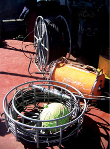
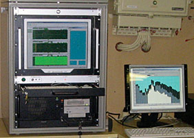
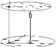
To experimentally explore a hydroacoustic field in shallow seas, a Marine autonomous measuring complex (MAMC) was designed under the supervision of B.M. Salin at the IAP RAS in the 1990s. The complex is intended for studying the acoustic field and noise characteristics of surface and underwater sources in a frequency range of up to 500 Hz. The MAMC is based on cable hydroacoustic antennas 200 m long with a self-contained system for data record.
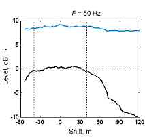
The technology and methods for the antenna use were significantly improved in the recent decade. The measurement metrology was provided by developing and certifying (A. S. Chashchin and B. V. Kiyashko) the digital hydroacoustic receivers (DHAR) with an integrated microcontroller. The inherent hydrophone noise does not exceed 35 dB rel. 20 μPa in the third-octave bands of an operating range of up to 10 kHz with a dynamic range no worse than 110 dB for an output digital signal according to the Ethernet protocol. The methods associated with the synthesis and adaptation of the directivity characteristics of multi-element distributed receiving systems to acoustic, hydrodynamic, and vibratory noise, which do not have any analogs, were developed and certified (V. I. Turchin and I. Sh. Fix). The noise suppression level was achieved at the antenna output, which was sufficient for solving almost any sort of the measuring problems.
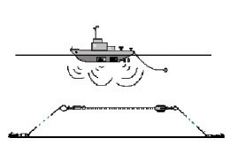
Antenna arrays can be used in various scientific and applied problems: for studying the spatial anisotropy of noise and the dynamics and fluctuations of signals on stationary paths, for selecting the signal modes in shallow water, for illuminating the underwater environment, for the near-field holography, and for the acoustic imaging of the underwater sources. Methods for synthesis of receiving systems with regard to both passive and active location were developed for these purposes at the IAP RAS. A theory for synthesis with the adaptation of the receiving system to the current noise characteristics has been elaborated (A. A. Rodionov). This approach, in particular, allows the antenna to be installed on board the ship, as the noise caused by the ship machinery is effectively suppressed.
The possibilities of linear antenna arrays of vertical and horizontal arrangements in the forward-scattering (transmissive) and bistatic sonar modes were theoretically and experimentally studied for active location.
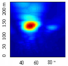
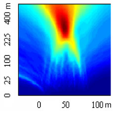
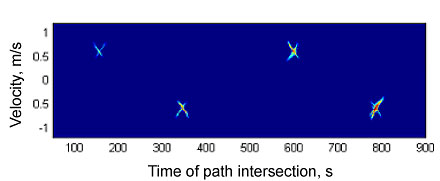
A time reversal method was implemented by employing receiving antennas in a marine experiment
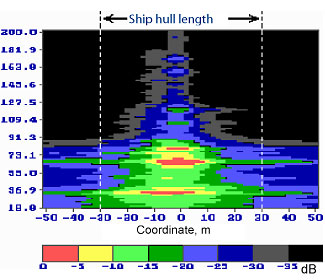
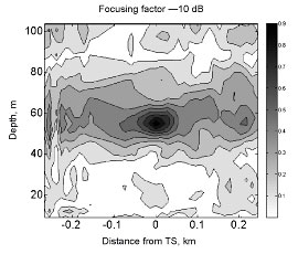
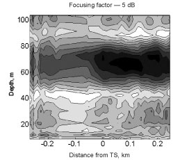
(A. A. Stromkov). A method for scanning the sources by hydroacoustic systems in a shallow sea using time reversal and a numerical model of the waveguide for range and depth focusing was proposed and experimentally tested (V. A. Zverev). To match the reception with the medium, the method uses the source signal inversion according to the well-known dispersion relations based on a numerical model of the waveguide.
|
|||||||||||||||||||||||||||||||||||||||||||||||||||||||||||||